Radiograph Positioning and Calibration for TPLO Planning
Quick answer
For TPLO planning, take a true lateral radiograph of the whole tibia with the stifle and tarsus at about 90°, the femoral condyles superimposed, and a calibration marker at the level of the bone. Then calibrate by measuring a known distance on the marker, because DICOM pixel spacing is defined at the detector and ignores magnification.
Key takeaways
- Positioning errors change the TPA; calibration errors change every millimeter in the plan.
- Include the whole tibia from stifle to tarsus; the talus defines the functional axis.
- X-ray magnification makes bone look larger than it is, often by several percent or more.
- Calibrate on a marker at bone level and use DICOM pixel spacing as a cross-check, not the final word.
Positioning: the true lateral view
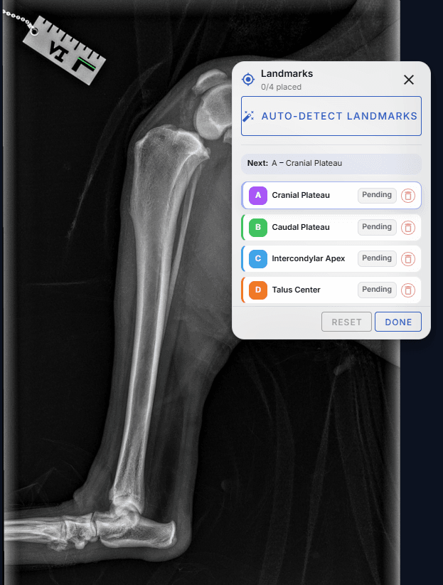
- Patient in lateral recumbency with the affected limb down, closest to the detector.
- Stifle and tarsus each flexed to about 90°.
- Femoral condyles superimposed. If they are split, the view is oblique and the plateau margins shift.
- Whole tibia in the image, including the stifle and the tarsus, so the intercondylar eminence and the center of the talus are both visible.
- Beam centered on the tibia to minimize divergence distortion at the joints.
Why magnification matters
X-rays diverge from the tube, so anything above the detector is projected larger than it really is. The magnification factor is the source-to-image distance divided by the source-to-object distance. With a 100 cm source-to-image distance and the tibia 10 cm above the detector, bone appears about 11% larger (100 ÷ 90).
Magnification = source-to-image distance ÷ source-to-object distance
Example: 100 cm ÷ 90 cm ≈ 1.11, so an uncalibrated 24 mm measurement is really about 21.6 mm.
For TPLO that affects blade selection, rotation distance, tuberosity width, and plate size. Angles such as the TPA are not changed by uniform magnification, but every length is.
Calibration markers
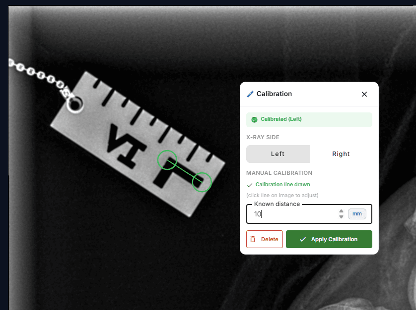
A calibration marker of known size (a notched ruler, a metal sphere of known diameter, or a marker like the one in these images) is placed at the same height above the detector as the tibia, so it is magnified by the same amount. Measuring it gives the true scale at the level of the bone.
- Place the marker at the level of the tibia, not flat on the detector.
- Measure the longest known distance available; a longer line reduces the effect of one pixel of placement error.
- Zoom in and put the calibration endpoints on the same edge of each notch.
DICOM pixel spacing: helpful, but not the whole story
Digital radiographs saved as DICOM usually carry pixel spacing metadata. Imager pixel spacing is defined at the detector plane, so on its own it describes the detector, not the magnified bone above it. Depending on the system and settings, a DICOM file may or may not include any magnification correction.
osAlign reads the DICOM pixel spacing and shows it next to your marker calibration so you can confirm the two agree, or see how much magnification you are correcting for.
Positioning and calibration checklist
- Femoral condyles superimposed
- Stifle to tarsus in one image; talus center visible
- Stifle and hock at about 90°
- Marker at the level of the bone, in the field of view
- Calibration line drawn on the longest known distance and applied
- DICOM pixel spacing checked against the marker calibration
- Correct side (left or right) selected
With a good image and calibration in place, move on to the step-by-step TPLO plan.
Frequently asked questions
Why do you need to calibrate a radiograph for TPLO?
Radiographs magnify bone depending on how far it is from the detector. Calibrating against a marker at the level of the bone converts pixels to true millimeters, so blade size, rotation distance, and plate size are correct.
Can I rely on DICOM pixel spacing instead of a calibration marker?
Use it as a cross-check. Imager pixel spacing is defined at the detector, not at the bone, so it does not by itself account for magnification. A marker at bone level is the reliable reference.
Does magnification change the tibial plateau angle?
Uniform magnification does not change angles, so the TPA is unaffected, but oblique positioning does change it. Magnification affects every length in the plan.
References
- Reif U, Dejardin LM, Probst CW, DeCamp CE, Flo GL, Johnson AL. Influence of limb positioning and measurement method on the magnitude of the tibial plateau angle. Vet Surg. 2004;33(4):368-375. https://pubmed.ncbi.nlm.nih.gov/15230840/
- Fettig AA, Rand WM, Sato AF, et al. Observer variability of tibial plateau slope measurement in 40 dogs with cruciate ligament-deficient stifle joints. Vet Surg. 2003;32(5):471-478. https://pubmed.ncbi.nlm.nih.gov/14569576/
- Assessment of the accuracy of digital surgical planning and its implementation with TPLO. Veterinary Research Communications (Springer), 2026. https://link.springer.com/article/10.1007/s11259-026-11253-w
- DICOM Standard, PS3.3: Imager Pixel Spacing (0018,1164) and Pixel Spacing (0028,0030) attribute definitions. https://dicom.nema.org/medical/dicom/current/output/chtml/part03/sect_10.7.html
For educational and planning support only. Surgeon judgment governs all clinical decisions.
Related guides
Plan your next TPLO in under 60 seconds
AI places the landmarks, the TPA is calculated instantly, and every measurement is reported to 0.1 mm. 30-day free trial with up to 5 cases, no credit card required.
Start free trial